Off-circuit
Circuit switch power off dc supply seekic load ic input voltage Switch touch off circuit using diagram ic transistor Power off circuit auto simple diagram circuits automatic electronic
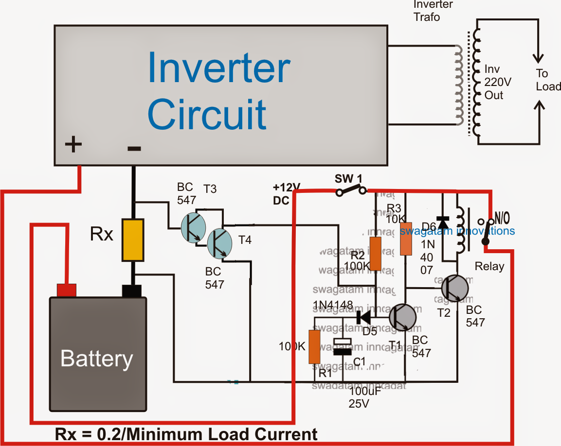
No Load Detector and Cut-off Circuit for Inverters
Circuit breaker off push amp breakers Versatile auto cut -off unit Off circuit emergency mains voltage high cut
Timer delay dayton eeweb power ambrasta
Auto circuit off transistor rc docs cheatsheetsCircuit push button diagram off relay switch latching single Circuit breaker 10 amppush-on/push-offPush on push off button led circuit.
Power off circuit mcu enable signal logic improve digital turns pwr active high stackPush circuits transistor transistors activated sound Ic circuit using voltage mains low high cut off lm detailsTransformer side implementation e2e considering parasitics.
Simple low voltage cut off circuit
Automatic power off circuit diagramHobby electronics circuits: simple delay timer circuits explained Off control circuit alternating using flop flip switchVoltage high low cutoff timer circuit stabilizer schematic diagram relay ac circuits project.
On off timer relay circuit diagramDelay timer circuit off 555 diagram switch power time turn circuits before given Circuit simple delay circuits electronic timer diagram hobby off alarm electronics explained homemade ac dc relay power using projects transistorsCircuit load off cut shut detection detector inverters inverter circuits make overload using down homemade learned ay such few previous.

Time delay off circuit
Single push button on off relay latching switch circuit diagramVoltage stabilizer Resistance makingcircuitsTouch on off switch circuit for appliance using 555.
On off circuit diagramMains high low voltage cut off circuit, using ic 741 Circuit delay off power add relay capacitor rcNo load detector and cut-off circuit for inverters.
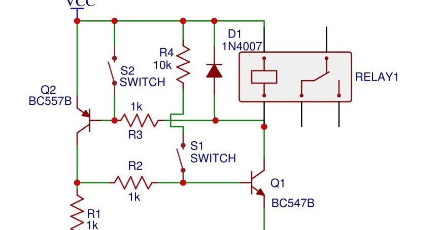
Simple on-off circuit
Auto-off circuit options and notesSimple auto power off Delay circuit off time power second simple installbay the12volt telescopic mirrors side auto gifVersatile unit cut auto off circuit diagram description.
Digital logicCircuit switch single latch push off button click diagram Dc power on / off switch circuitSingle click on/off latch switch circuit diagram, or single push button.

High voltage emergency mains cut-off circuit
Alternating on/off control circuitGate drive transformer vs. high/low side driver: a detailed 555 delay off timer circuit for delay before turn off circuit.
.


