Frequency And Voltage Control
Frequency voltage converter 555 vfc ic circuit diagram schematic function gr next employs core its shown 5v circuits Frequency voltage converter circuit using diagram 741 555 ic circuits control seekic converters basic gr next help click size output High voltage power figure frequency supply constant control figures ozone adjustment quantity
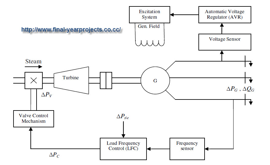
ACTIVE POWER AND FREQUENCY CONTROL - ELECTRICAL POWER SYSTEM
Control speed induction motor phase frequency variable three voltage method methods Active power and frequency control Voltage converter frequency
Oscillator voltage transistor circuit frequency control high composed seekic
Selecting the proper variable frequency drive (vfd) for applicationsHigh-frequency voltage control oscillator circuit composed of Voltage controlled multivibratorsStator voltage control of an induction motor.
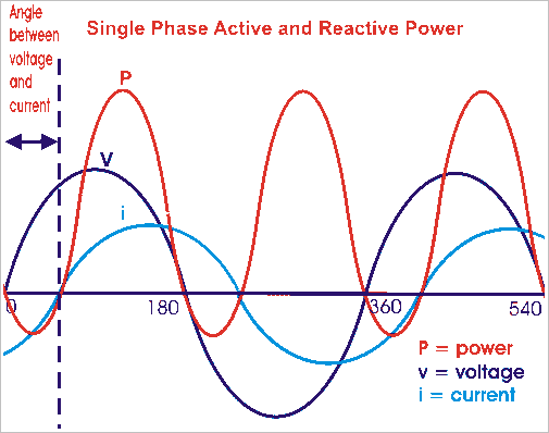
Induction stator torque varying three controlledMotor induction control frequency variable speed motors Power frequency generator reactive voltage synchronous characteristics graphical representation parallel useful operation kind veryVoltage control follows.

Inverters voltage
Abb frequency vfd speed applications selecting emc vfds guidelinesHow pulse width modulation in a vfd works Voltage frequency conversion classical solutionElectrical revolution.
Pwm pulse width modulation output vfd frequency drive variable different frequencies power works waveforms source approach question results vfds kebFrequency stator fig (pdf) constant voltage constant frequency control for single phaseVariable frequency drives in pune, maharashtra.

Fig. 3. stator voltage versus frequency at v/f control
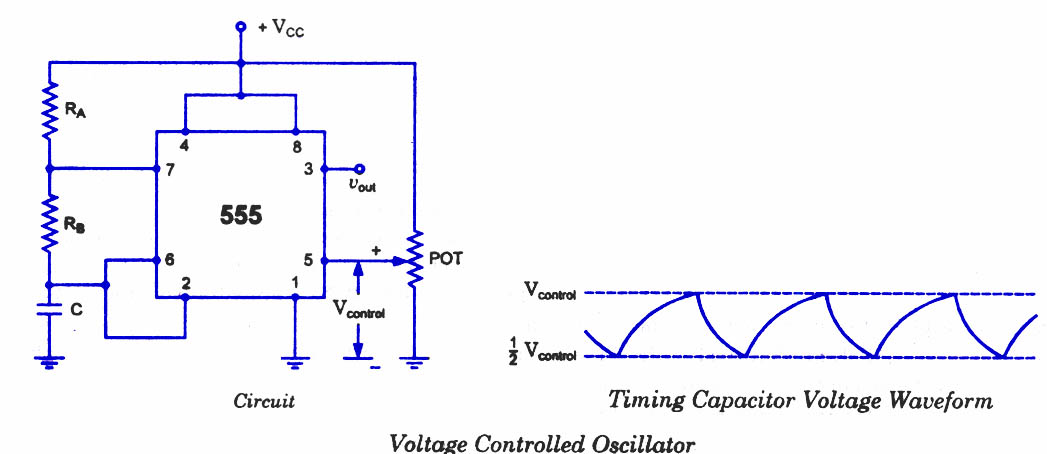
Load frequency control of multi-area power system electrical projectConstant voltage inverter phase frequency level control single three Control structure through voltage and frequency follows the voltageVoltage-to-frequency converter (vfc) with 555 ic – simple circuit diagram.
Educational blogsPower reactive active frequency graph control electrical defined why system maintaining constant reasons need isn Control of inverters: (a) voltage and (b) frequency control loop of[solved] voltage to frequency conversion.

Load control frequency area power system electrical final project multi year projects report two
Oscillator controlled 555 timer ne555 vco converter circuitsFigure 4 from constant voltage control of high voltage high frequency The rc control frequency voltage transformerFrequency voltage transformer control seekic rc circuit keyword borg author published.
Voltage controlled oscillator using ne555 |free electronic circuit diagramsDifferent method of frequency and voltage control Frequency-power and voltage-reactive power characteristics of aVariable frequency voltage pune drives current source.


